 |
FEATURES
Extremely low and stable leakage current characteristics.
Close capacitance tolerance ±20%(±10%).
 |
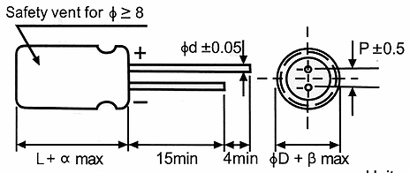
CASE SIZE TABLE
| ØD |
5 |
6,3 |
8 |
10 |
12,5 |
16 |
| P |
2,0 |
2,5 |
3,5 |
5,0 |
5,0 |
7,5 |
| Ød |
0,5 |
0,6 |
0,8 |
| α |
(L<20) 1,5 (L≥20) 2,0 |
| β |
(D<20) 0,5 (D≥20) 1,0 |
SPECIFICATIONS
| Item |
Performance Characteristics |
| Operating Temperature Range |
-40 to +105°C |
| Rated Working Voltage Range |
6,3 to 100V |
| Nominal Capacitance Range |
0,1 to 3300μF |
| Capacitance Tolerance |
±20% (120Hz, +20°C) |
| Leakage Current |
I ≤ 0,002 CV or 0,8(μA) whichever is greater measured after 2minutes application of with rated working voltage at +20°C |
Dissipation Factor
tan δ (120Hz, +20°C) |
| Working Voltage (V) |
6,3 |
10 |
16 |
25 |
35 |
50 |
63 |
100 |
| tan δ (max) |
0,28 |
0,24 |
0,20 |
0,16 |
0,14 |
0,12 |
0,10 |
0,08 |
For capacitance value >1000μF, add 0,02 per another 1000μF |
| Low Temperature Characteristics |
Impedance ratio max. at 120Hz
| Working Voltage (V) |
6,3 |
10 |
16 |
25 |
35 |
50 |
63 |
100 |
| Z-25°C / Z+20°C |
5 |
4 |
3 |
2 |
2 |
2 |
2 |
2 |
| Z-40°C / Z+20°C |
12 |
10 |
8 |
5 |
4 |
3 |
3 |
3 |
For capacitance value >1000μF,
Add 0,5 per another 1000μF for Z-25°C / Z+20°C
Add 1,0 per another 1000μF for Z-40°C / Z+20°C |
| High Temperature Loading |
| Test conditions |
Post test requirements at +20°C |
| Duration: 1000 hours |
Leakage current: ≤ Initial specified value |
| Ambient temp.: +105°C |
Cap. change: within ±20% of initial measured value |
| Applied voltage: Rated DC working voltage |
tan δ: ≤ 200% of initial specified value |
|
| Shelf Life |
| Test conditions |
Post test requirements at +20°C |
| Duration: 500 hours |
Leakage current: ≤ Initial specified value |
| Ambient temp.: +105°C |
Cap. change: within ±20% of initial measured value |
| Applied voltage: (None) |
tan δ: ≤ 200% of initial specified value |
|
STANDARD RATINGS
| Voltage (Code) |
6,3V |
10V |
16V |
25V |
| Cap, (μF) |
Case Size
ØDxL (mm) |
Ripple |
Case Size
ØDxL (mm) |
Ripple |
Case Size
ØDxL (mm) |
Ripple |
Case Size
ØDxL (mm) |
Ripple |
| 4,7 |
|
|
|
|
|
|
5x11 |
18 |
| 10 |
|
|
|
|
5x11 |
24 |
5x11 |
30 |
| 22 |
5x11 |
21 |
5x11 |
33 |
5x11 |
45 |
5x11 |
48 |
| 33 |
5x11 |
33 |
5x11 |
48 |
5x11 |
54 |
5x11 |
57 |
| 47 |
5x11 |
45 |
5x11 |
57 |
5x11 |
66 |
5x11 |
69 |
| 100 |
5x11 |
78 |
5x11 |
87 |
6,3x11 |
105 |
6,3x11 |
111 |
| 220 |
6,3x11 |
129 |
6,3x11 |
138 |
8x12 |
180 |
8x12 |
192 |
| 330 |
6,3x11 |
159 |
8x12 |
198 |
8x12 |
216 |
10x12,5 |
252 |
| 470 |
8x12 |
216 |
8x12 |
234 |
10x12,5 |
282 |
10x16 |
324 |
| 1000 |
10x12,5 |
342 |
10x16 |
378 |
10x20 |
474 |
12,5x20 |
570 |
| 2200 |
12,5x20 |
630 |
12,5x20 |
660 |
|
|
|
|
| 3300 |
12,5x20 |
750 |
|
|
|
|
|
|
| Maximum Allowable Ripple Current (mA rms) at 105°C 120Hz |
| Voltage (Code) |
35V |
50V |
63V |
100V |
| Cap, (μF) |
Case Size
ØDxL (mm) |
Ripple |
Case Size
ØDxL (mm) |
Ripple |
Case Size
ØDxL (mm) |
Ripple |
Case Size
ØDxL (mm) |
Ripple |
| 1 |
|
|
5x11 |
10 |
|
|
5x11 |
10 |
| 2,2 |
|
|
5x11 |
14 |
|
|
5x11 |
18 |
| 3,3 |
|
|
5x11 |
21 |
|
|
5x11 |
24 |
| 4,7 |
5x11 |
21 |
5x11 |
24 |
5x11 |
27 |
5x11 |
27 |
| 10 |
5x11 |
33 |
5x11 |
39 |
5x11 |
42 |
6,3x11 |
45 |
| 22 |
5x11 |
51 |
6,3x11 |
57 |
6,3x11 |
69 |
8x12 |
78 |
| 33 |
5x11 |
63 |
6,3x11 |
75 |
8x12 |
84 |
10x12,5 |
102 |
| 47 |
6,3x11 |
84 |
6,3x11 |
90 |
8x12 |
114 |
10x16 |
138 |
| 100 |
8x12 |
138 |
8x12 |
150 |
10x12,5 |
180 |
12,5x20 |
240 |
| 220 |
10x12,5 |
222 |
10x16 |
264 |
10x20 |
294 |
|
|
| 330 |
10x16 |
294 |
10x20 |
398 |
12,5x20 |
408 |
|
|
| 470 |
10x20 |
384 |
12,5x20 |
456 |
|
|
|
|
| Maximum Allowable Ripple Current (mA rms) at 105°C 120Hz |
RIPPLE CURRENT MULTIPLIER
Frequency Coefficient (Hz)
| Cap (μF) |
50 |
120 |
300 |
1k |
10k~ |
| ≤47 |
0,75 |
1,00 |
1,35 |
1,57 |
2,00 |
| 56-470 |
0,80 |
1,00 |
1,23 |
1,34 |
1,50 |
| 680-3300 |
0,80 |
1,00 |
1,1 |
1,13 |
1,50 |
TEMPERATURE COEFFICIENT
Frequency Coefficient (Hz)
| Temperature |
-55 |
60 |
70 |
85 |
105 |
| Factor |
2,23 |
2,17 |
2,00 |
1,75 |
1,00 |
|